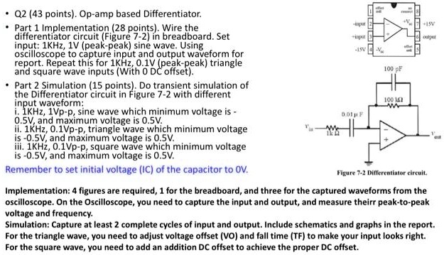
• Q2 (43 points). Op-amp based Differentiator.
Part 1 Implementation (28 points). Wire the
differentiator circuit (Figure 7-2) in breadboard. Set
input: 1KHz, 1V (peak-peak) sine wave. Using
oscilloscope to capture input and output waveform for
report. Repeat this for 1KHz, 0.1V (peak-peak) triangle
and square wave inputs (With 0 DC offset).
• Part 2 Simulation (15 points). Do transient simulation of
the Differentiator circuit in Figure 7-2 with different
input waveform:
i. 1KHz, 1Vp-p, sine wave which minimum voltage is -
0.5V, and maximum voltage is 0.5V.
ii. 1KHz, 0.1Vp-p, triangle wave which minimum voltage
is -0.5V, and maximum voltage is 0.5V.
iii. 1KHz, 0.1Vp-p, square wave which minimum voltage
is -0.5V, and maximum voltage is 0.5V.
Remember to set initial voltage (IC) of the capacitor to 0V.
Implementation: 4 figures are required, 1 for the breadboard, and three for the captured waveforms from the
oscilloscope. On the Oscilloscope, you need to capture the input and output, and measure theirr peak-to-peak
voltage and frequency.
Simulation: Capture at least 2 complete cycles of input and output. Include schematics and graphs in the report.
For the triangle wave, you need to adjust voltage offset (VO) and fall time (TF) to make your input looks right.
For the square wave, you need to add an addition DC offset to achieve the proper DC offset.